In this investigation you will explore series circuits and determine how the equivalent resistance is affected by combining more than one resistor.
Before you begin, click the Word or PDF link below to download your assignment worksheet. Then, read through the tabs below for the instructions. When you have completed the lab and the assignment, submit your worksheet to your teacher.
| Word |
Attribution: PhET Interactive Simulations | University of Colorado | https://phet.colorado.edu
The investigation consists of the parts shown below. Click the button below to download the instructions OR click through each tab to read and follow the steps to complete the investigation.
Exploring the Simulation
Calculating Equivalent Resistance


Click the “Intro” mode of the simulation.
In this part of the investigation, you will explore the simulation by creating a series circuit.
When you first open the simulation, a section on the left shows several choices of items that can be a part of your circuit. To use any of these items, click on it and drag it to the middle of the screen. You will use these items to create a series circuit.
On the right side of the screen is a section with a voltmeter and ammeter. To use either of these tools, click and drag it where you want to use it. When you are finished with it, you can put it away by clicking and dragging it back to the section on the right side of the screen.
Follow the directions in this slideshow to create a series circuit.


|
|
In the previous section you used lightbulbs as the resistance. You can also use resistors from the list of items on the left. In this section you will put multiple resistors together. The overall resistance produced from these resistors is called equivalent resistance. In this section you will determine how the equivalent resistance is calculated.


-
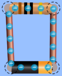
Click the “Reset” button. Drag a battery, two pieces of wire, and a resistor to the middle of the screen and connect them in a circuit similar to the one with the lightbulb you made for the last section.
-
Use the ammeter and voltmeter to measure the current and the voltage in this circuit. Answer Question 10 on your assignment worksheet.
-
Find the resistance using the equation V=IR and answer Question 11 on your assignment worksheet.
-
Click on the resistor and its resistance will appear at the bottom of the screen. Answer Question 12 on your assignment worksheet.
-
Break the circuit at the right corner between a wire and the resistor. Add another wire to the right side of the first resistor. Add another resistor and attach it to the 2 available ends of wire. Click on the second resistor and use the slider or right-facing arrow at the bottom of the screen to change its resistance to 20 Ω. Enter the resistance of each resistor in the data table on Question 13 of your assignment worksheet.
-
Use the voltmeter and ammeter to measure the voltage and current of the whole circuit. To measure the voltage, place the probes on the wires connected to either side of the battery. To measure the current, place the sensor on any of the wires. Record this data on the data table on Question 13 of your assignment worksheet.
-
Calculate the overall resistance and enter that on the data table on Question 13 of your assignment worksheet.
-
Cut the circuit after the second resistor and add another wire and resistor. Close the circuit and change the resistance of the third resistor to 30 Ω. Enter the resistance of each resistor in the data table on Question 14 of your assignment worksheet.
-
Measure the voltage and current of the whole circuit (as you did in step 6) and calculate the resistance for the circuit. Enter these values on the data table on Question 14 of your assignment worksheet.
-
Make one more circuit. Use 4 resistors and vary the resistances. Measure the voltage and current for each of the circuits and calculate the overall resistance. Enter your data on the data table on Question 15 of your assignment worksheet.
-
Study the individual resistances for each circuit and overall resistance for each circuit and answer Question 16 on your assignment worksheet.

